COMBINED LIGHTNING & VOLTAGE SURGE ARRESTER TYPE 1, 2 & 3: Imax 100KA/350µs
Product
group
HH
FOX.CLSPD1.4
Features
- Lightning Type 1 protection device
- Type 1, 2 & 3 combined
- Highest available protection level
- Total lightning current L1+L2+L3+N to PE 100KA 10/350µs
- Available in 4 pole, (three phase, 3 or 4 wire)
- Fully compliant to BSEN61643-11, BSEN62305 & BS7671
- Suitable for TNC-S & TN-S installations
- Flag visual status indication
- Auxiliary alarm output changeover contact
- PE terminals pre commoned via external bus-bar
- Din rail mounted
- Connected in parallel, no current limitations
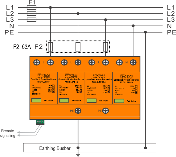
- To comply with BS7671 wiring regulations, 63 Amp backup fuse or MCB recommended

Direct lightning protection device, Type 1 100KA 10/350µs compliant to the latest standards, developed to protect against the effects of direct lightning strikes on an installation and the resultant induced voltages and surges. At the same time combined as a Type 1, 2 & 3 arrester to protect sensitive electronic equipment.
The units are four pole and therefore suitable for three phase applications, 3 wire or 4 wire. If a Neutral is present, it must be protected. Wiring is in parallel, therefore there is no maximum current limitations and in theory no discrimination fusing or MCB protection is required. However, within the UK to comply with BS7671 wiring regulations 534.4.5 and 534.4.5.2 it is required that back up discrimination fusing, or an MCB is utilised, a 63 Amp MCB is recommended.
The device has a mechanically driven flag indicator, green for healthy and red for fault. Additionally there is also a mechanically driven auxiliary C/O output contact, useful say as an alarm input into a BMS or PLC system. There being a healthy output status (between terminals 2 & 3), but also in the event of an MOV failing due to an intense or multiple surges the output contact will change state (between terminals 2 & 1), also indicated by a red flag on the failed MOV or MOV’s. In this state protection has been lost, the unit will need replacing.
Complies with: BSEN61643-11, BSEN62305 & BS7671
Protection via: High energy MOV’s (Metal Oxide Varistors)
Classification to BSEN61643-11: Type 1+2+3
Classification to IEC61643-1: Class I+II+III
Max total lightning current: 100KA (L1+L2+L3+N to PE)
Max per phase lightning current: 25KA (L/N to PE)
Nominal discharge current: 50KA 8/20µs (L/N to PE)
Response time: <100nS
Max AC continuous voltage: 255V L-N/L-E
Temporary overvoltage: 355V / 5 Secs
Thermal protection: Yes
Operating temperature: -40°C to +80°C
Discrimination fusing / MCB: Three pole 63 Amp MCB advised to comply with BS7671
Recommended cable size: 16mm² – 25mm² (25mm² recommended)
Installation cable length: < 1 metre as per BS7671:2018 Sec 534.4.8
Output contact rating: 250VAC / 0.5 Amps, AC1
TYPE
FOX.CLSPD1.4
Four pole type 1, 2 & 3 combined lightning and surge protection device, 100KA 10/350µs

Regulation 443.4.1
Protection against transient over voltages shall be provided where the consequences caused by over voltage could:-
i). Result in serious injury to, or loss of human life, or
ii). Result in failure of a safety service, as defined in Part 2, or
iii). Result in significant financial loss or data loss
For all other cases Surge Protection Devices shall be fitted to protect against transient over voltages, unless the owner of the installation declines such protection and wishes to accept the risk of damage to both wiring and equipment as tolerable.
Regulation 534.4.5
Protection of the Surge Protection Device against over current.
Surge Protection Device installations shall be protected against over current. This can be done with an MCB or a fuse.
Regulation 534.4.5.2
Arrangement of the Surge Protection Device with relation to over current protection.
In the case of an Over Current Protection Device operation arising from a Surge Protection Device failure, the continuity of supply must not be affected.
T Terra (Earth)
N Connection to Earth is via the supply network
C Stands for combined in relation to the Neutral and the Earth
S Stands for separate in relation to the Neutral and the Earth
Therefore TNC-S denotes a setup where the supply side of the system uses a combined Neutral and Earth conductor for Earthing.
The load side of the system uses a separate conductor for Earth and Neutral.
Therefore TN-S denotes a setup where the supply side of the system uses separate Neutral and Earth conductors, as does the load side.
PE Protective Earth
SPD Surge protection device
MOV Metal oxide varistors
